
Comprehensive Technical Support Documentation
Issue 3 – July 2005
T700 & T3000 information
has been removed to free up space for additional documents associated with
current models.
Use this CD in conjunction
with Issue 2 - July 2004.
A limited number of Issue 2
CD’s are still available from Tait Product Support Brisbane.
Introduction to
this Tait Documentation CD
Service Manual Updates (New CCT’s)
Tait Australia Application
Notes
Frequently Asked Questions
Service Manuals
|
T3000 Series
II Manual has been removed to make room for additional documents. Please
refer to the 2004 edition for this manual. |
|
T700 Servise
Manual has been removed to make room for additional documents. Please refer
to the 2004 edition for this manual. |
T800 Manuals
T5000/Orca Service
Manuals
T800 Series I Service Manuals
T800 Series II Service Manuals
T610 Inform Service Manual
Service Manual Updates
|
T3000 Series
II Manual updates have been removed to make room for additional documents.
Please refer to the 2004 edition of this CD for these updates. |
|
T700 Manual
updates have been removed to make room for additional documents. Please refer
to the 2004 edition of this CD for these updates. |
Tait Australia Application Notes
|
Wide Area Conventional PMR Systems – Containing
A800-SIM |
|
|
Unilab/Stanilite/ADI KL
Series Base Station Connection to A800-SIM |
|
|
A800-SIM3a
System Splitting |
|
|
Eclipse
70/150/500 Base Station Connection to A800-SIM |
|
|
T700 Simplex
Low Current ON & OFF Timer Operation |
|
|
MDS MX2000
KVC.1 Two Channel Audio Card E&M Positive Keying Modifications |
|
|
Interfacing
Tact TA-4800 to A800-SIM |
|
|
A800-SIM
Modified Fast CTCSS Keying |
|
|
Line Level
Setup Check List Of T800 Modules While Connected to a A800-SIM(V3) |
|
|
Solar powered
sites - standby battery low voltage disconnect. |
|
|
ADI-Spectra
MX800 Series Base Connection to A800-SIM |
|
|
A800-SIM3a
System Splitting (Using SEL_REC) |
|
|
T201X 9600 Baud
GMSK Modifications |
|
|
T800 Direct
Coupled DC FM Input |
|
|
MPT1327
Trunked Radio Direct Connect GPS |
|
|
Fitting 2
Remote Heads to a T2020 Radio. |
|
|
T800 Series II - T800V102 Firmware Information Current Version is
T800V102b |
|
|
T800-37 Paging
Line Modem Modifications for Increased Delay |
|
|
AN00-19 |
Not yet released. |
|
Increasing TB8100 Wide Band Maximum
Deviation |
Tech Notes 500-599
|
Tech Note |
Description |
|
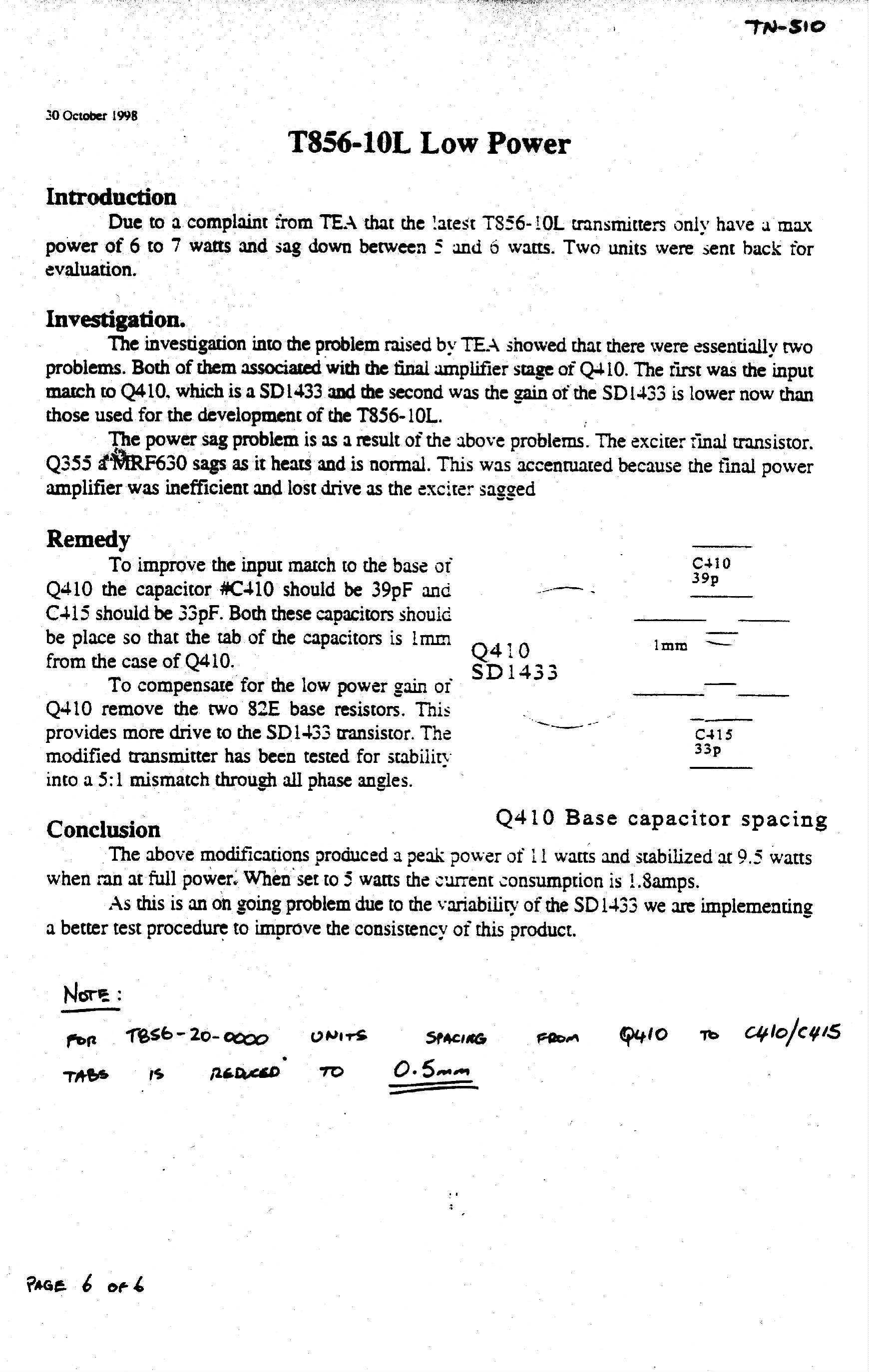
T856-10l Lower Power |
|
|
Combining Third Party Equipment With
The T800 Series II Radio Platform |
|
|
Tait Orca Conventional To Trunking
Conversion March 22, 1999 |
|
|
Improving The Noise Mute Performance
In Series II T855 Receivers |
|
|
T800 Series II - Fixed Equipment |
|
|
Radio Frequency Planner |
|
|
Tait Orca Elan Conventional Firmware |
|
|
Tait Orca Excel Conventional Firmware |
|
|
Modifications To The T2000 IF PCB. |
|
|
T3000 400-520mhz Radio Modifications |
|
|
Instruction For Fitting T2000-A66
(Uart) With T2000-A80 (Line Interface). |
|
|
How To Use The Site Select Feature On
A T2040. |
|
|
Instruction For Adjusting The X4
Multiplier In T2000 800mhz Radios. |
|
|
Tait Orca Transmit Audio Modification |
|
|
Tait Orca Performance Improvements |
|
|
Scrambler Modification For Use In
T2020. |
|
|
How To Make Sdm Calls With The T2040
& T3040. |
|
|
Developmental Summary Of Tait Orca
Battery Fit |
|
|
Tait Orca Trunking To Conventional
Conversion |
|
|
Tait Orca Antennas |
|
|
T800-02 CTCSS
Encoder/Decoder |
|
|
Tait Orca Elan
Conventional Firmware |
|
|
Tait Orca Excel
Conventional Firmware |
|
|
Tait Orca
Conventional To Trunking Upgrade Limitations |
|
|
New Software Help File Version 3.06 |
|
|
Introduction Of The T3000-1062 Is
Battery. |
|
|
Modification To The T2000-A50/A51
Hands Free Kit. |
|
|
T800 Fixed Equipment Modules |
|
|
T800 Series II Equipment List |
|
|
T800-07 Multi-Channel Memory PCB |
|
|
Re-Calibration Of T3000 Trunked Radio
‘L’ Levels |
|
|
Tait Orca Programming Software Ram
Requirements |
|
|
Topa-Ch-200 & T3002 Chargers New
V2.06 Software |
|
|
T700 Duplex Radios: Replacing 32v
Inverter Circuit With Nma1215s Device |
|
|
T889 PA De-Rating From 90w To 70w |
|
|
Changes To T3000 440 - 470mhz Radios |
|
|
Top-Xx21x Excel Conventional New
V1.07 Firmware Top Conventional New V1.10 Programming Software |
|
|
Instruction For Modifying A T201x
Radio For Fast Ptt Response. |
|
|
Replacing T800 Series I Equipment In
Taitnet Trunked Networks With The Series II Equivalent |
|
|
Choosing System Identity Codes And
Programming Radios For A Taitnet Network |
Tech Notes 600-699
|
Tech Note |
Description |
|
New Firmware For T3002 Fast Charger |
|
|
How To Use Group Select Features On
T2000 And T3000 |
|
|
1. Top-Xx11x Elan Conventional New
V1.07 Firmware 2. Top-Xx21x Excel Conventional New
V1.07 Firmware 3. Top Conventional New V1.11
Programming Software |
|
|
1. Top-Xx12x Elan Trunked New V3.03
Firmware 2. Top-Xx22x Excel Trunked New V3.03
Firmware 3. Top Trunked New V1.21 Programming
Software |
|
|
T889 Recommended Modification:
Replacing Q15/Q135 |
|
|
Tait Orca Accessory Topa-Aa-001 To
Topa-Aa-005 |
|
|
Introduction Of The T2000-A37 Selcall
Module |
|
|
Introduction Of New Feature On Hands
Free PCB. |
|
|
Introduction Of The 220-01344-05
Enhanced T2000 Logic |
|
|
Information On The Noise Blanker
Circuit Of The T2000 |
|
|
Introduction Of New IF Board For
T2000 Radios |
|
|
1. Top-Xx11x Elan Conventional New
V1.09 Firmware 2. Top-Xx21x Excel Conventional New
V1.09 Firmware |
|
|
1. Top-Xx31x Eclipse Conventional New
V1.07 Firmware |
|
|
1. Top Elan/Excel Trunked New V3.07
Firmware 2. Top Trunked New V1.25 Programming
Software |
|
|
Introduction Of New TCXO Module For
T2000 Radios |
|
|
New Stainless Steel Sma Connector |
|
|
Introduction Of The Sst 39sf010 Flash
Memory |
|
|
Using T830 Series I Equipment In A
T800 Series II Rack Frame |
|
|
1. Tait Orca Conventional Programming
Application V1.2.0 (Topcpa) 2. Tait Orca Download And
Configuration Application V1.2.0 (Topdlca) |
|
|
Remotely Controlling And Monitoring
Base Stations |
|
|
New Serial Numbers For T2000 Product
Range |
|
|
Tait Nicd Battery Care And
Maintenance (Based On Charger Software V2.06 Or Higher) |
|
|
Modifying A T800 II Programming Lead
For Use With The T1810 Channel Controller |
|
|
T2035 L.E.D. Display Messages |
|
|
1. Tait Orca Programming Utilities
V1.0 (Toptpu) 2. Tait Orca Conventional Programming
Application V2.0.0 (Topcpa) 3. Tait Orca Trunked Programming
Application V2.0.0 (Toptpa) 4. Tait Orca Calibration Application
V2.0.0 (Topcala) 5. Tait Orca Download And
Configuration Application V2.0.0 (Topdlca) |
|
|
T3000-1032 Nimh Battery Capacity
Changes |
|
|
Change To T3002 Fast Charger Software |
|
|
1. Tait Orca Charger Software V2.07 2. Tait Orca
Charger Pins 356-01079-00 |
|
|
Retrofitting Of New Charger Pin To
Old Charger PCBs |
|
|
Fitting A Heat-Spreader To A T889 PA |
|
|
T2020 Factory Software Upgrades |
|
|
T800-30-0000/0002 Dfsk Modulators |
|
|
1. Top Elan Trunked New V3.10
Firmware 2. Top Excel Trunked New V3.10
Firmware |
|
|
Installing Tait Line Despatcher
Terminals |
|
|
Line Despatcher Terminal Application
Note |
|
|
Changes To T3002 Fast Charger
Contacts. |
|
|
How To Use The Enhanced Scanning
Feature For The T2015 |
|
|
T2035 Factory Production Software
Upgrades. |
|
|
T2030 Error Code Display Messages |
|
|
Top Eclipse Charging In Vehicle Kit |
|
|
Tait Orca Portable 66-88mhz Sma
Antenna Connector |
|
|
T2040 Factory Production Software
Upgrades |
|
|
Upcoming Changes To The T2000 Screw
Types & Diecast Components. |
|
|
Programming A T1810 Channel
Controller |
|
|
Selecting Pabx Programmable Options
On The T1810 Channel Controller |
|
|
How To Use The Site Select Feature On
The T2035. |
|
|
Pc / Laptop Configuration
Requirements For Operating Tait Dos Pgm Software |
|
|
New Tait Orca 5000 Trunked Radio
Firmware And Programming Software |
|
|
New Top 5000 Chassis |
|
|
Introduction Of New Tait Orca 5000
Lens |
|
|
Dynamic Regrouping On T2000 And Tait
Orca |
|
|
Handportable Battery Facts and
Figures |
|
|
Firmware Upgrade for Orca 5000 Trunked Radios to
v4.09 |
|
|
Firmware Upgrade For Orca 5000
Conventional Radios To V2.02 |
|
|
Converting a T5000 Audio Accessory to an E series
Orca Accessory |
|
|
Tait Orca Accessory Modification
Update |
|
|
How
to use Group Select on a Tait Orca Elan, Excel, 5030, 5035 or 5040. |
Tech Notes 700-799
|
Tech Note |
Description |
|
Firmware Upgrade For The Tait Orca
5000 Mpt Trunked Radios To V4.12 |
|
|
Firmware Upgrade For The Tait Orca
5010 And 5020 Conventional Radios To V2.03 |
|
|
Firmware Upgrade For The Tait Orca
Elan, Excel And Eclipse Conventional Radios To V1.21 |
|
|
Ta 703-01 Firmware Upgrade |
|
|
New Tait Orca 5000 Chassis |
|
|
T201x’s Going Deaf On Channels With
No Tx Frequency |
|
|
Description - T2020 Voting |
|
|
Tait Orca Calibration Issue When
Setting The PA Bias |
|
|
Control Head Changes For The T2035 |
|
|
Modifying The Transmit Deviation Of
The T3000-4500 Plug-In CTCSS Board |
|
|
Power Problems With "-2xx"
66- 88mhz T2000s |
|
|
Correct Method For Removing The Tait
Orca Shield Sub-Assembly |
|
|
Firmware Upgrade For The Tait Orca
5010 And 5020 Conventional Radios To V2.05 |
|
|
Firmware Upgrade For The Tait Orca
5000 Mpt Trunked Radios To V4.13 |
|
|
Firmware Upgrade For The Tait Orca
5000 Mpt Trunked Radios To V4.14 |
|
|
Configuring TaitNet Networks for
Sharing Channel |
|
|
Firmware Upgrade For The Tait Orca
Élan, Excel And Eclipse Conventional Radios To V1.27 |
|
|
Enhanced Features For The Tait Orca
5000 Mpt Trunked And Conventional Radios |
|
|
Short Data Message (Sdm) Entry
Enhancement In The Orca 5035 And 5040 Portables |
|
|
Instructions For Fitting A Csi Dcs 23
Board To T800 Series 2 Equipment |
|
|
Production Release of T2010/15
Firmware V3.05 |
|
|
Firmware Upgrade For The Tait Orca
Élan And Excel MPT Trunked Radios To V3.15 |
|
|
Remotely Monitoring and Configuring
the TB8100 Base Station |
|
|
Using the TB8100 Base Station as a
Talk-Through, Community, or Linked Repeater |
|
|
Using the Tait TB8100 in
Tait Net Trunked Networks |
|
|
Changes To The T2000 Castings And
Screw Types Used |
|
|
Tait Orca 5000 Battery Charger
Operation |
|
|
Problems With Installing Windows
Programming Software Onto Windows 2000 & Win Xp |
|
|
Setting Up The External Alert Feature
In A T2000 |
|
|
Missing Test Point On T201x Logic
220-01377-07 |
|
|
CH Audio SW Mods for T1550, T1511 and
T1711 |
|
|
Identifying Damaged Tait Orca
Topa-An-202 Antennas |
|
|
Identifying Serial Number and Product
Codes |
|
|
Identifying the TOPA-AN-212 Antenna |
|
|
Upgrade of T2035 Firmware to Version
3.55 |
|
|
Upgrading the Tait Orca Vehicle Kit
to support Green Chassis |
|
|
Tait Orca and T3000 Charger Software
& Hardware Changes |
|
|
T1541 Validation and Registration
Diagnostics |
|
|
The TB8100 Calibration and Test Unit |
|
|
Upgrade of T2030 Firmware to V3.33 |
|
|
Re-Configuring a T610 Mobile Data
Terminal (MDT) that is displaying ‘Config code error’ |
|
|
An Explanation of the Nokia Actionet
Numbering System |
|
|
Actionet Numbering System Changes |
|
|
T836 Q425 Component Changes |
|
|
TOPA-AN-301 Cutting Chart Update |
|
|
Modification to the T2000-A37 Selcall
Module |
|
|
T2040 GPS Firmware V6.17 |
|
|
Software and Hardware Compatibility
for the TB8100 |
|
|
T2040 STD
Firmware V5.70 |
|
|
Orca VK Firmware Upgrade V1.05 |
Tech Notes 800-899
|
Tech Note |
Description |
|
T2000 software V2-55 release. |
|
|
Slow
Power Up of T2000's After a Firmware Upgrade. |
|
|
Introductions
to T2000-A46 Enhanced Signalling CTCSS Interface for T2030/35/40. |
|
|
TM8000
Mobile radio Release 2 Upgrade Instructions. |
|
|
TB8100
V 2.00 Product CD Release Notes |
|
|
Tait
Orca & Tait Orca 5000 Type Conversion Procedure |
|
|
TB8000 Hardware Dual Channel Subrack. |
|
|
Release of T2000 CNV & TRK software package version 2.64. |
|
|
T808-807
Power Supply DC Connector. |
|
|
Fuse
Crimp Connections on T800 Channel Rackframes |
|
|
Disabling
and Enabling Power Saving in the TB8000 Reciter |
|
|
T837
Paging Exciters Oscillation in IC240 |
|
|
TBA0M0x
Tone Remote Programming Application V1.08 |
|
|
TM8000
Direct Connect GPS |
|
|
TM8000
Mobile radio Release 3 and Upgrade Instructions |
|
|
Tait
Orca Programming Utilities TPU Upgrade V3.90 |
|
|
TOP
5000 Firmware 2.12 TOP CPA V3.90 |
|
|
TOP
5000 Firmware 4.26 TOP TPA V3.90 |
|
|
T1562
Line Dispatcher Software 5.01.08 |
|
|
TOP_Conventional_Programming_Applications_that_support_the_Tait_Radio_MODEM. |
|
|
T800
Programming Software V4.10. |
|
|
Release
of T2000 Programming Software_V2-71. |
|
|
New
T2000 TCXO Release |
|
|
TB8100_Calibration_Kit_Version_2_00_17 |
|
|
TM8100_Audio_Linking |
|
|
Upgrade
of T2040 firmware to V5.75 |
|
|
TBA0M0x
Tone Remote Programming Application V1.08.02 |
|
|
Measuring the Bit Error
Rate on TB9100 Base Stations |
Tech Notes 900-999
|
Tech Note |
Description |
|
Release
of T2040 GPS Firmware to V6-18. |
|
|
TM8100
Mobile Radio Firmware v2.02 Upgrade Instructions |
|
|
TM8100
Configuring the Stun feature |
|
|
New
T2000 Trunked Logic Board with on board UART |
|
|
Tait
Portables Programming Utilities Upgrade to v4.00.04 |
|
|
Tait
Orca 501, 5015, 5020 Firmware Upgrade to 2.14 & TOP-CPA Upgrade to 4.0.1 |
|
|
Tait
Orca 4030, 5035, 5040 Firmware Upgrade to 4.27 & TOP-TPA Upgrade to 4.0.1 |
|
|
TB8100
Base Station Release Notes - 1 October 2004 |
|
|
TM8000
Mobile Radio 10 Watt External Audio Output |
|
|
Production Change to Link-1 in TM8100
Mobile Radios |
|
|
TM8100 Mobile Radio Recalibration
Requirements |
|
|
TB8100
Taitnet RS232 SIF |
|
|
TM8000
Moible Radio Hardware Firmware Update |
|
|
Production Change to Calibrated L2
Level for the Tait Orca 5000 |
|
|
T2000-A37 Selcall Incompatibility with
TM8100 Mobile Radio |
|
|
T800 Paging Board Installation
Techniques to Preventing Loom Damage |
|
|
TB8100 base station Release Notes –
November 2004 |
|
|
TB8100 Base Station Computer Controlled
Interface (CCI) Protocol |
|
|
Tait
Portables Programming Utilities Upgrade
to v4.01.00 |
|
|
TM8200 Mobile
Radio Firmware v1.01 |
|
|
TB8100 V203
CD Release Notes – DRAFT |
|
|
TM81xx
firmware 2.04 and software 2.80 release note. |
|
|
How to
upgrade firmware in TM8100 and TM8200 radios |
|
|
T803-02
Firmware V2.15 |
|
|
TB8000
Software Release Notes |
|
|
TB9100
Firmware Upgrades Using TFTP |
|
|
TB9100
Replacing Network Board |
|
|
TM8000
Calibration Application Release v2.73 |
Tech Notes 1000-1099
|
Tech Note |
Description |
|
TM8100 PC App v2.80 correction and
Firmware v2.06 release. |
|
|
Rx Unmute Rules for the Digital
Terminal TM9000/TP9000. |
|
|
Tait Orca
Error Codes. |
|
|
T2000 Error
Codes. |
|
|
TM8100 Error
Codes. |
|
|
TM8200
Firmware Release V1.04 |
|
|
TB8100
Software Release Notes Service Pack 2.05. |
|
|
Tait
Portables Programming Utilities upgrade to V4-02-00. |
|
|
5010-5015-5018-5020
Firmware Upgrade to 2-15 & TOP-CPA Upgrade to 4-02-00. |
|
|
5030-5035-5040
Firmware Upgrade to 4-29 & TOP-TPA Upgrade to 4-02-00. |
|
|
TB7100 Tait
High Speed Data (THSD) |
|
|
TB8100 PMU Reset Modification. |
|
|
TB8100
Reciter May Reset when Calibrating VCO lock range. |
|
|
Tait Orca
Scanning & Voting |
|
|
Tait Orca PCB
Improvements |
|
|
TB7100 Base
Station Release Notes. |
|
|
Implementing
Channel Increment & Decrement on the TB7100. |
|
|
External
interfacing to the TM8000 AUX_GPI inputs |
|
|
Mobile
Duplexer Tuning Instructions |
Special Tech Notes
|
TM8000
Cross Band operation |
|
|
1200
Baud transparent data on TM8100 |
|
|
External
Alert Operation on T201X Radios |
User Guides & Supplements
TM8100
Guides
T2000
Guides
T2000 Smart Track AVL
T5000
Guides &
Supplements
User Manuals
T2000 User Manuals
ORCA User Manuals
T5000 User Manuals
|
T5010 Users Manual Not yet
available |
|
T5020 Users Manual Not yet
available |
|
T5030 Users Manual Not yet
available |
|
T5035 Users Manual Not yet
available |
|
T5040 Users Manual Not yet
available |
T5015 User Manual
Programming User Manuals
Operator Manuals
|
T3000
Operator Manuals have been removed to make room for additional documents.
Please refer to the 2004 edition for these manuals. |
T2000 Service Manual Updates
|
RF Board 66-88 Mhz |
|
|
RF Board 66-88 Mhz |
|
|
RF Board 66-88 Mhz |
|
|
RF Board 175-225 Mhz |
|
|
RF Board 400-520 Mhz |
|
|
RF Board 400-520 Mhz |
|
|
T2020 ENHANCED LOGIC CONTROL BOARD |
|
|
T2020 Control/Logic Board |
|
|
Hands Free Interface Board |
|
|
Hands Free Interface Board |
|
|
Dual Port Uart Board |
|
|
Line Interface Board |
|
|
RF Board 330-380 Mhz |
|
|
RF
Board 330-380 Mhz |
|
|
RF
Board 330-380 Mhz |
|
|
RF
Board 330-380 Mhz |
|
|
RF
Board 800 Mhz |
|
|
Selcall Board |
|
|
RF Board 136-174 Mhz |
|
|
RF Board 136-174 Mhz |
|
|
RF Board 136-174 Mhz |
|
|
RF Board 136-174 Mhz |
|
|
Control Head T2010 |
|
|
Control Head T2010/30 |
|
|
Control Head T2015 |
|
|
Control Head T2015 |
|
|
Control Head T2020/40/50 |
|
|
Control Head T2020/40/50 |
|
|
Control Head T2020/40/50 |
|
|
Control Head T2035 |
|
|
Cnv Preset Control Board |
|
|
RF Board 220-270 Mhz |
|
|
Control Board T2020-40-50 |
|
|
Ctcss-Scrambler Board |
|
|
Control/Logic Board T2020-40-50 |
|
|
Control/Logic Board T2020-40-50 |
|
|
Control/Logic Board T2020-40-50 |
|
|
Control/Logic Board T2020-40-50 |
|
|
Control/Logic Board T2020-40-50 |
|
|
Control/Logic Board T2020-40-50 |
|
|
Control/Logic Board T2020-40-50 |
|
|
Control/Logic Board T2020-40-50 |
|
|
Control/Logic Board T2020-40-50 |
|
|
Control/Logic Board T2020-40-50 |
|
|
Control/Logic Board T2020-40-50 |
|
|
Single Port Uart Board |
|
|
Control/Logic Board T2010/15 |
|
|
Control/Logic Board T2010/15 |
|
|
Control/Logic Board T2010/15 |
|
|
Control/Logic Board T2010/15 |
|
|
Control/Logic Board T2010/15 |
|
|
Control/Logic Board T2010/15 |
|
|
Control/Logic Board T2010/15 |
|
|
Control/Logic Board T2010/15 |
|
|
Control/Logic Board T2010/15 |
|
|
Control/Logic Board T2010/15 |
|
|
Data Modem Board |
|
|
IF Board |
|
|
Emc Board |
|
|
IF Board |
|
|
IF Board |
|
|
Data Interface De-Coupling Board |
|
|
Data Interface De-Coupling Board |
|
|
RF Board 330-380 Mhz |
|
|
Tcxo Board |
|
|
Tcxo Board |
|
|
Dual Bandwidth If Board |
|
|
Control Head T2015/35 |
|
|
Data Interface De-Coupling Board |
|
|
Selcall Board |
|
|
RF Board 800-900 Mhz |
|
|
LTR Control/Logic Board |
|
|
Dual Bandwidth Control/Logic Board |
|
|
Options Board |
|
|
Tcxo Board 2.5Khz offset |
|
|
Tcxo Board 2.5Khz offset |
|
|
RF Board 800-900 Mhz |
|
|
Raywood Interface Board |
|
|
IF Assembled Board Part Numbers |
Raywood Interface Board
|
Raywood Interface Board |
|
|
Raywood Interface Board |
|
|
Raywood Interface Board |
|
|
Raywood Interface Board |
|
|
Raywood Interface Board |
|
|
Raywood Interface Board |
|
|
IF Assembled Board Part Numbers |
T5000 Various Board Updates
|
Circuit Diagram And Board Layouts
400-470 Mhz |
|
|
Circuit Diagram And Board Layouts
400-470 Mhz |
|
|
Circuit Diagram And Board Layouts
400-470 Mhz |
|
|
Circuit Diagram And Board Layouts
400-470 Mhz |
|
|
Circuit Diagram And Board Layouts
400-470 Mhz |
|
|
Circuit Diagram And Board Layouts
400-470 Mhz |
|
|
Circuit Diagram And Board Layouts
400-470 Mhz |
|
|
Circuit Diagram And Board Layouts
400-470 Mhz |
|
|
Circuit Diagram And Board Layouts
400-470 Mhz |
|
|
Circuit Diagram And Board Layouts
400-470 Mhz |
|
|
Circuit Diagram And Board Layouts
400-470 Mhz |
|
|
Circuit Diagram And Board Layouts
400-470 Mhz |
|
|
Circuit Diagram And Board Layouts
400-470 Mhz |
|
|
Circuit Diagram And Board Layouts
400-470 Mhz |
|
|
Circuit Diagram And Board Layouts
400-470 Mhz |
|
|
Circuit Diagram And Board Layouts
400-470 Mhz |
|
|
Circuit Diagram And Board Layouts
400-470 Mhz |
|
|
Circuit Diagram And Board Layouts
400-470 Mhz |
|
|
Circuit Diagram And Board Layouts
400-470 Mhz |
|
|
Circuit Diagram And Board Layouts
400-470 Mhz |
|
|
Circuit Diagram And Board Layouts
400-470 Mhz |
|
|
Circuit Diagram And Board Layouts
400-470 Mhz |
|
|
Circuit Diagram And Board Layouts
400-470 Mhz |
|
|
Circuit Diagram And Board Layouts
400-470 Mhz |
|
|
Circuit Diagram And Board Layouts
400-470 Mhz |
|
|
Circuit Diagram And Board Layouts
136-174 Mhz |
|
|
Circuit Diagram And Board Layouts
136-174 Mhz |
|
|
Circuit Diagram And Board Layouts
136-174 Mhz |
|
|
Circuit Diagram And Board Layouts
136-174 Mhz |
|
|
Circuit Diagram And Board Layouts
136-174 Mhz |
|
|
Circuit Diagram And Board Layouts 136-174
Mhz |
|
|
Circuit Diagram And Board Layouts
136-174 Mhz |
|
|
Circuit Diagram And Board Layouts
136-174 Mhz |
|
|
Circuit Diagram And Board Layouts
136-174 Mhz |
|
|
Circuit Diagram And Board Layouts
136-174 Mhz |
|
|
Circuit Diagram And Board Layouts
136-174 Mhz |
|
|
Circuit Diagram And Board Layouts
136-174 Mhz |
|
|
Circuit Diagram And Board Layouts
136-174 Mhz |
|
|
Circuit Diagram And Board Layouts
136-174 Mhz |
|
|
Fast Charger |
|
|
Fast Charger |
|
|
Fast Charger |
|
|
Fast Charger |
|
|
Fast Charger |
|
|
Fast Charger |
|
|
Fast Charger |
|
|
Fast Charger |
|
|
Fast Charger |
|
|
Fast Charger |
|
|
Fast Charger |
|
|
Keypad Interface |
|
|
Keypad Interface |
|
|
Keypad Interface |
|
|
Keypad Interface |
|
|
Keypad Interface |
|
|
Keypad Interface |
|
|
Keypad Interface |
|
|
Keypad Interface |
|
|
Keypad Interface |
|
|
Auxiliary Connector |
|
|
Auxiliary Connector |
|
|
Auxiliary Connector |
|
|
Auxiliary Connector |
|
|
Auxiliary Connector |
|
|
Auxiliary Connector |
|
|
Aux Flex |
|
|
Aux Flex |
|
|
Aux Flex |
|
|
Circuit Diagram And Board Layouts 800
Mhz |
|
|
Circuit Diagram And Board Layouts 800
Mhz |
|
|
Circuit Diagram And Board Layouts 800
Mhz |
|
|
Circuit Diagram And Board Layouts 800
Mhz |
|
|
Circuit Diagram And Board Layouts 800
Mhz |
|
|
Battery Eliminator |
|
|
Battery Eliminator |
|
|
Calibration Board |
|
|
Programming PCB |
|
|
Programming PCB |
|
|
Programming PCB |
|
|
Programming PCB |
|
|
Programming PCB |
|
|
User Interface Flex |
|
|
Auxiliary Connector PCB Motorola |
|
|
Auxiliary Connector PCB Motorola |
|
|
Auxiliary Connector PCB Motorola |
|
|
Auxiliary Connector PCB Motorola |
|
|
Auxiliary Connector PCB Motorola |
|
|
Auxiliary Connector PCB Motorola |
|
|
Auxiliary Connector PCB Motorola |
|
|
Auxiliary Connector PCB Motorola |
|
|
Circuit Diagram And Board Layouts
336-400 Mhz |
|
|
Circuit Diagram And Board Layouts
336-400 Mhz |
|
|
Circuit Diagram And Board Layouts
336-400 Mhz |
|
|
Circuit Diagram And Board Layouts
336-400 Mhz |
|
|
Circuit Diagram And Board Layouts
336-400 Mhz |
|
|
Circuit Diagram And Board Layouts
336-400 Mhz |
|
|
Circuit Diagram And Board Layouts
336-400 Mhz |
|
|
Circuit Diagram And Board Layouts
336-400 Mhz |
|
|
Circuit Diagram And Board Layouts
336-400 Mhz |
|
|
Circuit Diagram And Board Layouts
336-400 Mhz |
|
|
Circuit Diagram And Board Layouts
336-400 Mhz |
|
|
Circuit Diagram And Board Layouts
336-400 Mhz |
|
|
Circuit Diagram And Board Layouts
336-400 Mhz |
|
|
Circuit Diagram And Board Layouts
336-400 Mhz |
|
|
Circuit Diagram And Board Layouts
336-400 Mhz |
|
|
Circuit Diagram And Board Layouts
336-400 Mhz |
|
|
Circuit Diagram And Board Layouts
336-400 Mhz |
|
|
Circuit Diagram And Board Layouts
336-400 Mhz |
|
|
Circuit Diagram And Board Layouts
336-400 Mhz |
|
|
Circuit Diagram And Board Layouts
336-400 Mhz |
|
|
Circuit Diagram And Board Layouts
336-400 Mhz |
|
|
Circuit Diagram And Board Layouts
336-400 Mhz |
|
|
Circuit Diagram And Board Layouts
336-400 Mhz |
|
|
Circuit Diagram And Board Layouts
336-400 Mhz |
|
|
Circuit Diagram And Board Layouts
336-400 Mhz |
|
|
Tait Orca Series Car Kit Charger Pcb |
|
|
Tait Orca Series Car Kit Charger Pcb |
|
|
Tait Orca Series Car Kit Charger Pcb |
|
|
Tait Orca Series Car Kit Charger Pcb |
|
|
Tait Orca Series Car Kit Charger Pcb |
|
|
Tait Orca Series Car Kit Charger Pcb |
|
|
Tait Orca Series Car Kit Charger Pcb |
|
|
Tait Orca Series Car Kit Charger Pcb |
|
|
Tait Orca Series Car Kit Charger Pcb |
|
|
Tait Orca Series Car Kit Options Board |
|
|
Tait Orca Series Car Kit Options Board |
|
|
Tait Orca Series Car Kit Options Board |
|
|
Tait Orca Series Car Kit Options Board |
|
|
Tait Orca Series Car Kit Options Board |
|
|
Tait Orca Series Car Kit Options Board |
|
|
Tait Orca Series Car Kit Options Board |
|
|
Tait Orca Series Car Kit Options Board |
|
|
Tait Orca Series Car Kit Accessory Probe Pcb |
|
|
Tait Orca Series Car Kit Accessory Probe Pcb |
|
|
Tait Orca Series Car Kit Accessory Probe Pcb |
|
|
Tait Orca Series Car Kit Accessory Probe Pcb |
|
|
Tait Orca Series Car Kit Accessory Probe Pcb |
|
|
Accessory Speaker Mic PCB |
|
|
Accessory Speaker Mic PCB |
|
|
Accessory Speaker Mic PCB |
|
|
Accessory Speaker Mic PCB |
|
|
Accessory Speaker Mic PCB |
|
|
Radio Calibration Cable |
|
|
Car Kit Probe PCB |
|
|
Car Kit Probe PCB |
|
|
Circuit Diagram And Board Layouts
450-530 Mhz |
|
|
Circuit Diagram And Board Layouts
450-530 Mhz |
|
|
Circuit Diagram And Board Layouts
136-174 Mhz |
|
|
Circuit Diagram And Board Layouts
136-174 Mhz |
|
|
Circuit Diagram And Board Layouts
136-174 Mhz |
|
|
Circuit Diagram And Board Layouts
136-174 Mhz |
|
|
Circuit Diagram And Board Layouts
136-174 Mhz |
|
|
Circuit Diagram And Board Layouts
136-174 Mhz |
|
|
Circuit Diagram And Board Layouts
136-174 Mhz |
|
|
Circuit Diagram And Board Layouts
136-174 Mhz |
|
|
Circuit Diagram And Board Layouts
136-174 Mhz |
|
|
Circuit Diagram And Board Layouts
136-174 Mhz |
|
|
Circuit Diagram And Board Layouts
136-174 Mhz |
|
|
Circuit Diagram And Board Layouts
136-174 Mhz |
|
|
Circuit Diagram And Board Layouts
136-174 Mhz |
|
|
Circuit Diagram And Board Layouts
136-174 Mhz |
|
|
Circuit Diagram And Board Layouts
400-470 Mhz |
|
|
Circuit Diagram And Board Layouts
400-470 Mhz |
|
|
Circuit Diagram And Board Layouts
400-470 Mhz |
|
|
Circuit Diagram And Board Layouts
400-470 Mhz |
|
|
Circuit Diagram And Board Layouts
400-470 Mhz |
|
|
Circuit Diagram And Board Layouts
400-470 Mhz |
|
|
Circuit Diagram And Board Layouts
400-470 Mhz |
|
|
Circuit Diagram And Board Layouts
400-470 Mhz |
|
|
Circuit Diagram And Board Layouts
400-470 Mhz |
|
|
Circuit Diagram And Board Layouts
400-470 Mhz |
|
|
Circuit Diagram And Board Layouts
400-470 Mhz |
|
|
Circuit Diagram And Board Layouts
400-470 Mhz |
|
|
Circuit Diagram And Board Layouts
400-470 Mhz |
|
|
Circuit Diagram And Board Layouts
400-470 Mhz |
|
|
Circuit Diagram And Board Layouts
400-470 Mhz |
|
|
Circuit Diagram And Board Layouts
400-470 Mhz |
|
|
Circuit Diagram And Board Layouts
800-900 Mhz |
|
|
Circuit Diagram And Board Layouts
800-900 Mhz |
|
|
Circuit Diagram And Board Layouts
800-900 Mhz |
|
|
Circuit Diagram And Board Layouts
800-900 Mhz |
|
|
Circuit Diagram And Board Layouts
800-900 Mhz |
|
|
Circuit Diagram And Board Layouts
800-900 Mhz |
|
|
Circuit Diagram And Board Layouts
800-900 Mhz |
|
|
Circuit Diagram And Board Layouts
800-900 Mhz |
|
|
Circuit Diagram And Board Layouts
800-900 Mhz |
|
|
Circuit Diagram And Board Layouts
800-900 Mhz |
|
|
Circuit Diagram And Board Layouts
800-900 Mhz |
|
|
Circuit Diagram And Board Layouts
800-900 Mhz |
|
|
Circuit Diagram And Board Layouts
800-900 Mhz |
|
|
Circuit Diagram And Board Layouts
800-900 Mhz |
|
|
Circuit Diagram And Board Layouts
800-900 Mhz |
|
|
Circuit Diagram And Board Layouts 66-88
Mhz |
|
|
Circuit Diagram And Board Layouts
66-88 Mhz |
|
|
Circuit Diagram And Board Layouts
66-88 Mhz |
|
|
Circuit Diagram And Board Layouts
66-88 Mhz |
|
|
Circuit Diagram And Board Layouts
66-88 Mhz |
|
|
Circuit Diagram And Board Layouts
66-88 Mhz |
|
|
Circuit Diagram And Board Layouts
66-88 Mhz |
|
|
Circuit Diagram And Board Layouts
66-88 Mhz |
|
|
Circuit Diagram And Board Layouts
66-88 Mhz |
|
|
Circuit Diagram And Board Layouts
66-88 Mhz |
|
|
Circuit Diagram And Board Layouts
66-88 Mhz |
|
|
Circuit Diagram And Board Layouts
66-88 Mhz |
|
|
Circuit Diagram And Board Layouts
66-88 Mhz |
|
|
Circuit Diagram And Board Layouts
450-530 Mhz |
|
|
Circuit Diagram And Board Layouts
450-530 Mhz |
|
|
Circuit Diagram And Board Layouts
450-530 Mhz |
|
|
Circuit Diagram And Board Layouts
450-530 Mhz |
|
|
Circuit Diagram And Board Layouts
450-530 Mhz |
|
|
Circuit Diagram And Board Layouts
450-530 Mhz |
|
|
Circuit Diagram And Board Layouts
450-530 Mhz |
|
|
Circuit Diagram And Board Layouts
450-530 Mhz |
|
|
Circuit Diagram And Board Layouts
450-530 Mhz |
|
|
Circuit Diagram And Board Layouts
450-530 Mhz |
|
|
Circuit Diagram And Board Layouts
450-530 Mhz |
|
|
Circuit Diagram And Board Layouts
450-530 Mhz |
|
|
Circuit Diagram And Board Layouts
450-530 Mhz |
|
|
Circuit Diagram And Board Layouts
450-530 Mhz |
|
|
Keypad Interface |
|
|
Keypad Interface |
|
|
Keypad Interface |
|
|
Keypad Interface |
|
|
Keypad Interface |
|
|
Keypad Interface |
|
|
Keypad Interface |
|
|
Circuit Diagram And Board Layouts
174-225 Mhz |
|
|
Circuit Diagram And Board Layouts
174-225 Mhz |
|
|
Circuit Diagram And Board Layouts
174-225 Mhz |
|
|
Circuit Diagram And Board Layouts
174-225 Mhz |
|
|
Circuit Diagram And Board Layouts
174-225 Mhz |
|
|
Circuit Diagram And Board Layouts
174-225 Mhz |
|
|
Circuit Diagram And Board Layouts
174-225 Mhz |
|
|
Circuit Diagram And Board Layouts
174-225 Mhz |
TM8100 Service Manual Updates
|
Main Board UHF |
|
|
Main Board UHF |
|
|
Main Board UHF (Information pack) |
|
|
Main Board VHF (Information pack) |
|
|
Control Head TM8115 (Information
pack) |
|
|
|
Dummy Head TM8105 (No drawings yet available) |
|
TM8000 Programming Cable |
TB8000 Service Manual Updates
|
|
No information yet available. |
T800 Various Service Manual Updates
|
T850/T870 VCO |
|
|
T850/T870 PCB Layout |
|
|
T807/T808 PCB Layout |
|
|
T807/T808 PCB Layout |
|
|
T889 800mhz 90w PA |
|
|
T889 800mhz 90w PA |
|
|
T889 800mhz 90w PA |
|
|
T889 800mhz 90w PA |
|
|
T889 800mhz 90w PA |
|
|
T889 800mhz 90w PA |
|
|
T837 Exciter |
|
|
T800-50
Backplane |
|
|
T800-50
Backplane |
|
|
T800-50
Backplane |
|
|
T800-50
Backplane |
|
|
T800-50
Backplane |
|
|
T859 PCB Layouts and CCT’s |
|
|
T858
PCB Layouts and CCT’s |
|
|
T800-60-0000
Backplane Issue 00A |
|
|
T800-50-0001
Backplane Issue 02A |
|
|
T800-50-0001
Backplane Issue 03A |
|
|
T800-50-0001
Backplane Issue 04A |
|
|
T800-50-0001
Backplane Issue 05A |
|
|
T800-50-0001
Backplane Issue 06A |
|
|
T800-52-0000
Backplane Issue 03A |
|
|
T800-52-0000
Backplane Issue 04A |
|
|
T800-52-0000
Backplane Issue 05A |
|
|
T800-52-0000
Backplane Issue 06A |
|
|
T800-52-0000
Backplane Issue 07A |
|
|
T825
Receiver |
|
|
T825
Receiver |
|
|
T803
Tone Remote Panel |
|
|
Pin
Functions Of Backplane Receive Only / Ch-Pnl / Alarms |
|
|
Pin
Functions Of Backplane Receive Only / Ch-Pnl / Alarms |
|
|
Pin
Functions Of Backplane Receive Only / Ch-Pnl / Alarms |
|
|
Pin
Functions Of Backplane Receive Only / Ch-Pnl / Alarms |
|
|
Backplane
Rx-Only+Ch/Pnl+Alarm |
|
|
T881 800mhz TX |
|
|
T881 800mhz TX |
|
|
T881 800mhz TX |
|
|
T881 800mhz TX |
|
|
T881 800mhz TX |
|
|
T881 800mhz TX |
|
|
T800-55-0000
Backplane PCB |
|
|
T800-60-0002
Backplane |
|
|
T800-60-0001
Backplane |
|
|
T800-50-0003
Backplane |
|
|
T800-50-0003
Backplane |
|
|
T885
Receiver Board circuits and layouts |
|
|
T885
Receiver Board circuits and layouts |
|
|
T885
Receiver Board circuits and layouts |
|
|
T885
Receiver Board circuits and layouts |
|
|
T885
Receiver Board circuits and layouts |
|
|
T885
Receiver Board circuits and layouts |
|
|
Pin
Functions Of Personality Board Alarms (0v) + Channel Panel |
|
|
T800-37
Modem/Delay Unit |
|
|
T800-37
Modem/Delay Unit |
|
|
T800-37
Modem/Delay Unit |
|
|
T800-56-0000
Liberty 100w Backplane |
|
|
Pin
Functions Of T800-56-700x Backplane |
|
|
T800-56-0001
Liberty Slimline Backplane |
|
|
T800-56-0002
Bsm Slimline Backplane |
|
|
T800-56-0002
Bsm Slimline Backplane |
|
|
NB-WB
Personality T800-60-0003 |
|
|
Dual
External Reference Backplane |
|
|
Dual
receiver, one speaker panel. |
|
|
T800 Alarm Interface. |
|
|
T800 Alarm Interface. |
|
Rack Assembly |
|
|
T800 Rack Frame Reference Guide Issue
100 |
|
|
T800 Rack Frame Reference Guide Issue
101 |
|
|
T800 Rack Frames |
|
|
T800 Rack configuration Information |
T1500 Service Manual Updates
|
T1500-56-0000 Series II 50/100w
Backplane |
|
|
T1500-56-0000 Series II 50/100w
Backplane |
|
|
T1500-56-0000 Series II 50/100w
Backplane |
|
|
T1500-52 TX Alarm
Interface |
T820 Series I Service Manual
|
Pages
1-10 |
|
|
Pages
AI-AII |
|
|
Pages
A1.1-A1.2 |
|
|
Pages
A2.1-A2.2 |
|
|
Pages A3.1-A3.2 |
|
|
Pages A4.1-A4.2 |
|
|
Pages A5.1-A5.2 |
|
|
Pages A6.1-A6.2 |
|
|
Pages
A7.1-A7.4 |
|
|
Pages A8.1-A8-2 |
|
|
Pages BI-BII |
|
|
Pages B1.1-B1.8 |
|
|
Pages B2.1-B2.12 |
|
|
Pages B3.1-B3.12 |
|
|
Pages B4.1-B4.8 |
|
|
Pages B5.1-B5.14 |
|
|
Pages B6.1.1-B6.1.4 |
|
|
Pages B6.2.1-B6.2.20 |
|
|
Pages CI-CII |
|
|
Pages C1.1-C1.8 |
|
|
Pages C2.1-C2.12 |
|
|
Pages C3.1-C3.14 |
|
|
Pages C4.1-C4.6 |
|
|
Pages C5.1-C5.14 |
|
|
Pages C6.1.1-C6.1.4 |
|
|
Pages C6.2.1-C6.2.20 |
|
|
Pages C6.3.1-C6.3.18 |
|
|
Pages DI-DII |
|
|
Pages D1.1-D1.6 |
|
|
Pages D2.1-D2.8 |
|
|
Pages D3.1-D3.8 |
|
|
Pages D4.1-D4.8 |
|
|
Pages D5.1.1-D5.1.4 |
|
|
Pages D5.2.1-D5.2.12 |
|
|
Pages EI-EII |
|
|
Pages E1.1-E1.2 |
|
|
Pages E2.1-E2.6 |
|
|
Pages E3.1-E3.8 |
|
|
Pages FI-FII |
|
|
Pages F1.1-F1.4 |
|
|
Pages F2.1-F2.4 |
|
|
Pages
GI-GII |
|
|
Pages
G1.1-G1.2 |
|
|
Pages
G2.1-G2.2 |
|
|
Pages G3.1-G3.2 |
|
|
Pages G4.1-G4.2 |
|
|
Pages G5.1-G5.2 |
|
|
Pages HI-HII |
|
|
Pages H1-H6 |
T820 II Service Manual
|
Pages 1-4 |
|
|
Pages AI-AII |
|
|
Pages
A1.1-A1.2 |
|
|
Pages A2.1-A2.4 |
|
|
Pages A3.1-A3.2 |
|
|
Pages
A4.1-A4.2 |
|
|
Pages BI-BII |
|
|
Pages B1.1-B1.12 |
|
|
Pages B2.1-B2.12 |
|
|
Pages B3.1-B3.14 |
|
|
Pages B6.1.1-B6.1.6 |
|
|
Pages B6.2.1-B6.2.14 |
|
|
Pages B6.2.15-B6.2.26 |
|
|
Pages B6.3.15-B6.3.26 |
|
|
Pages CI-CII |
|
|
Pages C1.1-C1.10 |
|
|
Pages C2.1-C2.14 |
|
|
Pages C3.1-C3.14 |
|
|
Pages C6.1.1-C6.1.6 |
|
|
Pages C6.2.1-C6.2.14 |
|
|
Pages C6.2.15-C6.2.26 |
|
|
Pages C6.3.1-C6.3.14 |
|
|
Pages C6.3.15-C6.3.26 |
|
|
Pages DI-DII |
|
|
Pages D1.1-D1.8 |
|
|
Pages D2.1-D2.6 |
|
|
Pages D3.1-D3.8 |
|
|
Pages D4.1-D4.10 |
|
|
Pages D5.1.1-D5.1.6 |
|
|
Pages D5.2.1-D5.2.8 |
|
|
Pages D5.2.9-D5.2.12 |
|
|
Pages EI-EII |
|
|
Pages E1.1-E1.4 |
|
|
Pages E2.1-E2.8 |
|
|
Pages E2.9-E2.10 |
T830 Series I Service Manual
|
Pages 1-10 |
|
|
Pages AI-AII |
|
|
Pages A1.1-A1.2 |
|
|
Pages
A2.1-A2.2 |
|
|
Pages A3.1-A3.2 |
|
|
Pages A4.1-A4.2 |
|
|
Pages A5.1-A5.2 |
|
|
Pages A6.1-A6.2 |
|
|
Pages
A7.1-A7.2 |
|
|
Pages A8.1-A8.2 |
|
|
Pages BI-BII |
|
|
Pages B1.1-B1.8 |
|
|
Pages B2.1-B2.10 |
|
|
Pages B3.1-B3.12 |
|
|
Pages B4.1-B4.8 |
|
|
Pages B5.1-B5.14 |
|
|
Pages B6.1.1-B6.1.4 |
|
|
Pages B6.2.1-B6.2.20 |
|
|
Pages CI-CII |
|
|
Pages C1.1-C1.8 |
|
|
Pages C2.1-C2.10 |
|
|
Pages C3.1-C3.14 |
|
|
Pages C4.1-C4.6 |
|
|
Pages C5.1-C5.14 |
|
|
Pages C6.1.1-C6.1.4 |
|
|
Pages C6.2.1-C6.2.24 |
|
|
Pages DI-DII |
|
|
Pages D1.1-D1.6 |
|
|
Pages D2.1-D2.6 |
|
|
Pages D3.1-D3.8 |
|
|
Pages D4.1-D4.8 |
|
|
Pages D5.1.1-D5.1.4 |
|
|
Pages EI-EII |
|
|
Pages E1.1-E1.2 |
|
|
Pages E2.1-E2.6 |
|
|
Pages E3.1-E3.8 |
|
|
Pages FI-FII |
|
|
Pages F1.1-F1.4 |
|
|
Pages F2.1-F2.4 |
|
|
Pages
GI-GII |
|
|
Pages
G1.1-G1.2 |
|
|
Pages
G2.1-G2.2 |
|
|
Pages G3.1-G3.2 |
|
|
Pages G4.1-G4.2 |
|
|
Pages G5.1-G5.2 |
|
|
Pages HI-HII |
|
|
Pages H1-H6 |
T830 II Service Manual
|
Pages 1-12 |
|
|
Pages AI-AII |
|
|
Pages A1.1-A1.2 |
|
|
Pages
A2.1-A2.4 |
|
|
Pages A3.1-A3.2 |
|
|
Pages
A4.1-A4.2 |
|
|
Pages BI-BII |
|
|
Pages B1.1-B1.14 |
|
|
Pages B1.3-B1.4 |
|
|
Pages B2.1-B2.12 |
|
|
Pages B3.1-B3.14 |
|
|
Pages
B4.1-B4.8 |
|
|
Pages B4.9-B4.10 |
|
|
Pages B5.1-B5.20 |
|
|
Pages B6.1.1-B6.1.6 |
|
|
Pages B6.2.1-B6.2.16 |
|
|
Pages B6.2.11-B6.2.12 |
|
|
Pages B6.2.17-B6.2.30 |
|
|
Pages CI-CII |
|
|
Pages C1.1-C1.16 |
|
|
Pages C1.3-C1.6 |
|
|
Pages C2.1-C2.14 |
|
|
Pages C3.1-C3.14 |
|
|
Pages C4.1-C4.8 |
|
|
Pages C4.9-C4.12 |
|
|
Pages C5.1-C5.20 |
|
|
Pages C6.1.1-C6.1.6 |
|
|
Pages C6.2.11-C6.2.12 |
|
|
Pages C6.2.1-C6.2.16 |
|
|
Pages C6.2.17-C6.2.28 |
|
|
Pages C6.3.11-C6.3.12 |
|
|
Pages C6.3.17-C6.3.28 |
|
|
Pages C6.3.1-C6.3.16 |
|
|
Pages C6.3.29-C6.3.42 |
|
|
Pages C6.3.37-C6.3.38 |
|
|
Pages C6.3.43-C6.3.54 |
|
|
Pages DI-DII |
|
|
Pages D1.1-D1.10 |
|
|
Pages D1.3-D1.4 |
|
|
Pages D2.1-D2.8 |
|
|
Pages D3.1-D3.8 |
|
|
Pages D3.9-D3.10 |
|
|
Pages D4.1-D4.14 |
|
|
Pages D4.5-D4.6 |
|
|
Pages D5.1.1-D5.1.6 |
|
|
Pages D5.2.11-D5.2.14 |
|
|
Pages D5.2.1-D5.2.10 |
|
|
Pages D5.2.7-D5.2.8 |
|
|
Pages D5.3.13-D5.3.16 |
|
|
Pages D5.3.1-D5.3.12 |
|
|
Pages D5.3.9-D5.3.10 |
|
|
Pages EI-EII |
|
|
Pages E1.1-E1.4 |
|
|
Pages E2.11-E2.16 |
|
|
Pages E2.17-E2.18 |
|
|
Pages E2.1-E2.8 |
|
|
Pages E2.9-E2-10 |
|
|
Pages FI-FII |
|
|
Pages F1.1-F1.2 |
|
|
Pages F2.1-F2.2 |
|
|
Pages F3.1-F3.2 |
|
|
Pages F4.1-F4.2 |
|
|
Pages
GI-GII |
|
|
Pages
G1.1-G1.4 |
|
|
Pages
G2.1-G2.4 |
|
|
Pages G3.1-G3.2 |
|
|
Pages G4.1-G4.2 |
|
|
Pages G5.1-G5.2 |
|
|
Pages HI-HII |
|
|
Pages H1-H14 |
|
|
Pages II-IIi |
|
|
Pages
I1.1-I1.2 |
|
|
Pages
I2.1-I2.8 |
|
|
Pages
I3.1-I3.6 |
T830p II Service Manual
|
Pages 1-4 |
|
|
Pages AI-AII |
|
|
Pages
A1.1-A1.2 |
|
|
Pages A2.1-A2.4 |
|
|
Pages A3.1-A3.2 |
|
|
Pages
A4.1-A4.2 |
|
|
Pages CI-CII |
|
|
Pages C1.1-C1.12 |
|
|
Pages C2.1-C2.14 |
|
|
Pages C3.1-C3.8 |
|
|
Pages C4.1-C4.4 |
|
|
Pages C5.1-C5.14 |
|
|
Pages C6.1.1-C6.1.6 |
|
|
Pages C6.2.1-C6.2.12 |
|
|
Pages DI-DII |
|
|
Pages D1.1-D1.10 |
|
|
Pages D2.1-D2.8 |
|
|
Pages D3.1-D3.6 |
|
|
Pages D4.1-D4.14 |
|
|
Pages D5.1.1-D5.1.6 |
|
|
Pages D5.2.1-D5.2.12 |
|
|
Pages D5.3.1-D5.3.12 |
|
|
Pages EI-EII |
|
|
Pages E1.1-E1.4 |
|
|
Pages E2.1-E2.8 |
|
|
Pages FI-FII |
|
|
Pages F3.1-F3.2 |
|
|
Pages GI-GII |
|
|
Pages G1.1-G1.2 |
|
|
Pages G2.1-G2.4 |
|
|
Pages HI-HII |
|
|
Pages H1-H8 |
|
|
T830P Circuit & board layouts (To be added) |
Pages |
T850 Series I Service Manual
|
Pages 1-12 |
|
|
Pages AI-AII |
|
|
Pages A1.1-A1.2 |
|
|
Pages
A2.1-A2.2 |
|
|
Pages A3.1-A3.2 |
|
|
Pages A4.1-A4.2 |
|
|
Pages A5.1-A5.2 |
|
|
Pages A6.1-A6.2 |
|
|
To Fit The
Optional T800-55 High Sensitivity Preamplifier To a T855 |
Pages A7.1-A7.2 |
|
Pages
A8.1-A8.4 |
|
|
Pages A9.1-A9.2 |
|
|
Pages BI-BII |
|
|
Pages B1.1-B1.8 |
|
|
Pages B2.1-B2.12 |
|
|
Pages B3.1-B3.14 |
|
|
Pages B4.1-B4.8 |
|
|
Pages B5.1-B5.14 |
|
|
Pages B6.1.1-B6.1.4 |
|
|
Pages B6.2.1-B6.2.8 |
|
|
Pages B6.3.1-B6.3.4 |
|
|
Pages B6.4.1-B6.4.38 |
|
|
Pages CI-CII |
|
|
Pages C1.1-C1.10 |
|
|
Pages C2.1-C2.12 |
|
|
Pages C3.1-C3.14 |
|
|
Pages C4.1-C4.6 |
|
|
Pages C5.1-C5.14 |
|
|
Pages C6.1.1-C6.1.4 |
|
|
Pages C6.2.1-C6.2.40 |
|
|
Pages C6.3.1-C6.3.66 |
|
|
Pages DI-DII |
|
|
Pages D1.1-D1.6 |
|
|
Pages D2.1-D2.8 |
|
|
Pages D3.1-D3.10 |
|
|
Pages D4.1-D4.12 |
|
|
Pages D5.1.1-D5.1.4 |
|
|
Pages D5.2.1-D5.2.12 |
|
|
Pages D5.2.1-D5.3.14 |
|
|
Pages EI-EII |
|
|
Pages E1.1-E1.2 |
|
|
Pages E2.1-E2.6 |
|
|
Pages E3.1-E3.12 |
|
|
Pages FI-FII |
|
|
Pages F1.1-F1.4 |
|
|
Pages F2.1-F2.4 |
|
|
Pages
GI-GII |
|
|
Pages
G1.1-G1.2 |
|
|
Pages
G2.1-G2.2 |
|
|
Pages G3.1-G3.2 |
|
|
Pages G4.1-G4.2 |
|
|
Pages G5.1-G5.2 |
|
|
Pages HI-HII |
|
|
Pages H1-H8 |
T850 II Service Manual
|
Pages 1-12 |
|
|
Pages AI-AII |
|
|
Pages
A1.1-A1.2 |
|
|
Pages A2.1-A2.4 |
|
|
Pages A3.1-A3.2 |
|
|
Pages
A4.1-A4.2 |
|
|
Pages BI-BII |
|
|
Pages B1.1-B1.14 |
|
|
Pages B1.3-B1.4 |
|
|
Pages B2.1-B2.12 |
|
|
Pages B3.1-B3.14 |
|
|
Pages B4.1-B4.8 |
|
|
Pages B4.9-B4.10 |
|
|
Pages B5.1-B5.20 |
|
|
Pages B6.1.1-B6.1.6 |
|
|
Pages B6.2.1-B6.2.6 |
|
|
Pages B6.2.7-B6.2.8 |
|
|
Pages B6.3.11-B6.3.12 |
|
|
Pages B6.3.1-B6.3.16 |
|
|
Pages B6.3.17-B6.3.30 |
|
|
Pages B6.3.31-B6.3.44 |
|
|
Pages B6.3.39-B6.3.40 |
|
|
Pages B6.3.45-B6.3.58 |
|
|
Pages CI-CII |
|
|
Pages C1.1-C1.16 |
|
|
Pages C1.3-C1.6 |
|
|
Pages C2.1-C2.14 |
|
|
Pages C3.1-C3.14 |
|
|
Pages C4.1-C4.8 |
|
|
Pages C4.9-C4.12 |
|
|
Pages C5.1-C5.20 |
|
|
Pages C6.1.1-C6.1.6 |
|
|
Pages C6.2.11-C6.2.12 |
|
|
Pages C6.2.17-C6.2.30 |
|
|
Pages C6.2.1-C6.2.16 |
|
|
Pages C6.3.15-C6.3.28 |
|
|
Pages C6.3.1-C6.3.14 |
|
|
Pages C6.3.29-C6.3.42 |
|
|
Pages C6.3.37-C6.3.38 |
|
|
Pages C6.3.43-C6.3.56 |
|
|
Pages C6.3.9-C6.3.10 |
|
|
Pages DI-DII |
|
|
Pages D1.1-D1.18 |
|
|
Pages D1.5-D1.12 |
|
|
Pages D2.1-D2.16 |
|
|
Pages D3.15-D3.22 |
|
|
Pages D3.1-D3.14 |
|
|
Pages D4.1-D4.32 |
|
|
Pages D4.21-D4.22 |
|
|
Pages D4.5-D4.6 |
|
|
Pages D5.1.1-D5.1.6 |
|
|
Pages D5.2.13-D5.2.16 |
|
|
Pages D5.2.1-D5.2.26 |
|
|
Pages D5.2.23-D5.2.24 |
|
|
Pages D5.2.27-D5.2.30 |
|
|
Pages D5.2.9-D5.2.10 |
|
|
Pages D5.3.12 |
|
|
Pages D5.3.13-D5.3.16 |
|
|
Pages D5.3.17-D5.3.26 |
|
|
Pages D5.3.1-D5.3.11 |
|
|
Pages D5.3.23-D5.3.24 |
|
|
Pages D5.3.27-D5.3.30 |
|
|
Pages D5.3.9-D5.3.10 |
|
|
Pages EI-EII |
|
|
Pages E1.1-E1.2 |
|
|
Pages E2.1-E2.6 |
|
|
Pages E2.7-E2.8 |
|
|
Pages FI-FII |
|
|
Pages F1.1-F1.2 |
|
|
Pages F2.1-F2.2 |
|
|
Pages F3.1-F3.2 |
|
|
Pages F4.1-F4.2 |
|
|
Pages
GI-GII |
|
|
Pages
G1.1-G1.4 |
|
|
Pages
G2.1-G2.4 |
|
|
Pages G3.1-G3.2 |
|
|
Pages G4.1-G4.2 |
|
|
Pages HI-HII |
|
|
Pages H1-H14 |
|
|
Pages II-III |
|
|
Pages
I1.1-I1.2 |
|
|
Pages
I2.1-I2.8 |
|
|
Pages
I3.1-I3.8 |
T880 Series I Service Manual
T880 II Service Manual
|
Pages 1-4 |
|
|
Pages AI-AII |
|
|
Pages
A1.1-A1.2 |
|
|
Pages A2.1-A2.6 |
|
|
Pages A3.1-A3.2 |
|
|
Pages
A4.1-A4.2 |
|
|
Pages BI-BII |
|
|
Pages B1.1-B1.12 |
|
|
Pages B2.1-B2.12 |
|
|
Pages B3.1-B3.14 |
|
|
Pages B6.1.6-B6.1.6 |
|
|
Pages B6.2.1-B6.2.14 |
|
|
Pages B6.2.15-B6.2.26 |
|
|
Pages CI-CII |
|
|
Pages C1.1-C1.10 |
|
|
Pages C2.1-C2.12 |
|
|
Pages C3.1-C3.14 |
|
|
Pages C6.1.1-C6.1.6 |
|
|
Pages C6.2.1-C6.2.14 |
|
|
Pages C6.2.15-C6.2.26 |
|
|
Pages DI-DII |
|
|
Pages D1.1-D1.8 |
|
|
Pages D2.1-D2.8 |
|
|
Pages D3.1-D3.6 |
|
|
Pages D4.1-D4.14 |
|
|
Pages D4.5-D4.6 |
|
|
Pages D5.1.1-D5.1.6 |
|
|
Pages D5.2.1-D5.2.10 |
|
|
Pages D5.2.11-D5.2.14 |
T800 I Ancillary Equipment Manual
|
Pages 1-8 |
|
|
Pages AI-AII |
|
|
Pages A1.1-A1.2 |
|
|
Pages A2.1-A2.2 |
|
|
Pages A3.1-A3.2 |
|
|
Pages A4.1-A4.2 |
|
|
Pages A5.1-A5.4 |
|
|
Pages A6.1-A6.2 |
|
|
Pages BI-BII |
|
|
Pages B1.1-B1.10 |
|
|
Pages B2.1-B2.6 |
|
|
Pages B3.1-B3.10 |
|
|
Pages B4.1-B4.6 |
|
|
Pages B5.1-B5.4 |
|
|
Pages B6.1-B6.10 |
|
|
Pages B7.1-B7.8 |
|
|
Pages B8.1.1-B8.1.4 |
|
|
Pages
B8.2.1-B8.2.60 |
T800 II Ancillary Equipment Manual
|
Pages
1-8 |
|
|
Pages AI-AII |
|
|
Pages
A1.1-A1.2 |
|
|
Pages A2.1-A2.2 |
|
|
Pages A3.1-A3.2 |
|
|
Pages A4.1-A4.2 |
|
|
Pages
A5.1-A5.4 |
|
|
Pages A6.1-A6.2 |
|
|
Pages BI-BII |
|
|
Pages B1.1-B1.10 |
|
|
Pages B2.1-B2.6 |
|
|
Pages B3.1-B3.10 |
|
|
Pages B4.1-B4.6 |
|
|
Pages B5.1-B5.4 |
|
|
Pages B6.1-B6.10 |
|
|
Pages B7.1-B7.8 |
|
|
Pages B8.1.1-B8.1.4 |
|
|
Pages B8.2.7 |
|
|
Pages B8.2.9-B8.2.16 |
|
|
Pages B8.2.18-B8.2.29 |
|
|
Pages B8.2.31-B8.2.38 |
|
|
Pages B8.2.40 |
|
|
Pages B8.2.42 |
|
|
Pages B8.2.44 |
|
|
Pages B8.2.47 |
|
|
Pages B8.2.58 |
|
|
Pages B8.2.60 |
|
|
Pages B8.2.62 |
|
|
Pages CI-CII |
|
|
Pages C1.1-C1.10 |
|
|
Pages C2.1-C2.10 |
|
|
Pages C3.1.1-C3.1.4 |
|
|
Pages C3.2.1-C3.2.10 |
|
|
Pages C3.2.12 |
|
|
Pages C3.2.14-C3.2.15 |
|
|
Pages C3.3.1-C3.3.12 |
|
|
Pages C3.3.5-C3.3.9 |
Orca "E" Series Service Manual
|
Pages I-IV |
|
|
Pages A3-A10 |
|
|
Pages B3-B8 |
|
|
Pages C3-C14 |
|
|
Pages D3-D14 |
|
|
Pages E3-E14 |
|
|
Pages F3-F8 |
|
|
Pages G3-G8 |
T5000 Service Manual
|
Introduction |
|
|
Pages A1-A14 |
|
|
Pages B1-B16 |
|
|
Pages C1-C14 |
|
|
Pages D1-D20 |
|
|
Pages E1-E16 |
|
|
Pages F1-F26 |
|
|
Pages G1-G8 |
T5000
Green
|
|
|
|
Introduction |
|
|
Pages A1-A12 |
|
|
Pages B1-B20 |
|
|
Pages C1-C14 |
|
|
Pages D1-D22 |
|
|
Pages E1-E16 |
|
|
Pages F1-F24 |
|
|
Pages G1-G9 |
T5000 Intrinsically Safe Addition
ORCA/T5000 Vehicle Kit Service Manual
T2000 Service Manual Sections.
|
Pages 1-18 |
|
|
Pages 1.1-1.10 |
|
|
Pages 2.1-2.20 |
|
|
Pages
3.1-3.18 |
|
|
Pages
4.1-4.12 |
|
|
Pages
5.1-5.32 |
|
|
Pages 6.1-6.10 |
|
|
Pages 7.1-7.4 |
|
|
Pages 7.1.1-7.1.10 |
|
|
Pages 7.2.1-7.2.10 |
|
|
Pages 7.3.1-7.3.10 |
|
|
Pages 7.4.1-7.4.10 |
|
|
Pages 7.5.1-7.5.12 |
|
|
Pages 7.6.1-7.6.10 |
|
|
Pages 7.7.1-7.7.10 |
|
|
Pages 7.8.1-7.8.6 |
|
|
Pages 7.9.1-7.9.6 |
|
|
Pages 7.10.1-7.10.12 |
|
|
Pages 7.11.1-7.11.12 |
|
|
Pages 7.12.1-7.12.6 |
|
|
Pages 7.13.1-7.13.6 |
|
|
Pages 7.14.1-7.14.8 |
|
|
Pages 7.15.1-7.15.6 |
|
|
Pages 7.16.1-7.16.6 |
|
|
Pages 7.17.1-7.17.6 |
|
|
Pages 8.1-8.2 |
|
|
Pages 8.1.1-8.1.24 |
|
|
Pages 8.2.1-8.2.2 |
|
|
Pages
8.3.1-8.3.4 |
|
|
Pages 8.4.1-8.4.2 |
|
|
Pages 8.5.1-8.5.4 |
|
|
Pages 8.6.1-8.6.4 |
|
|
Pages 8.7.1-8.7.4 |
|
|
Pages 8.8.1-8.8.8 |
|
|
Pages 8.9.1-8.9.2 |
|
|
Pages 8.10.1-8.10.10 |
|
|
Pages 8.11.1-8.11.18 |
|
|
Pages 8.12.1-8.12.14 |
|
|
Pages 8.13.1-8.13.8 |
|
|
Pages 8.14.1-8.14.28 |
|
|
Pages 8.15.1-8.15.18 |
|
|
Pages 8.16.1-8.16.8 |
|
|
Pages
9.1-9.8 |
Aditional Documentation
|
T3000
Additional Information has been removed to make room for additional
documents. Please refer to the 2004 edition for this information. |
|
T700
Additional Information has been removed to make room for additional
documents. Please refer to the 2004 edition for this information. |
T5000 / Orca Documents
T5000 Aerial Cutting Charts
TM8000 Mobile Documentation
TB8000 Base Station Documentation
T5000/ORCA Charger Circuits and Board Information
|
Not currently available. |
|
|
T2000
Documentation
|
T2000 RAD Radtel Interface
Card. (No Longer Available, Use the T2000-UIS). |
|
Tait
Portable Repeater Case Brochure And Fitting Instructions |
Raywood Interface Board
|
Raywood Interface Board |
|
|
Raywood Interface Board |
|
|
Raywood Interface Board |
|
|
Raywood Interface Board |
|
|
Raywood Interface Board |
|
|
Raywood Interface Board |
T2000-A75
Modem
T2000-A76
AVL Modem
|
T800-22-0021 Drawing - 25watt Base
Station/Repeater With 10 Amp Circuit Breaker Panel Plus Monitor Rx/Tx And Channel Panel Options |
T800-37 Modem Delay Board
T801-00 Reference Module
|
T801-00 Reference Module part 1 Not yet available |
|
T801-00 Reference Module part 2 Not yet available |
T703 Changeover Module
T5000 Conventional Menu Charts
T5000 Trunking Menu Charts
T2000 Conformity Documents
TB8000 Manuals
Calibration Kit User’s Manual
|
Service
Kit User’s Manual
|
TB8100 Service
Manual
|
TB
8100 Specification Manual
|
TB8100
TBA0M01 Tone Remote and TBA0M02 Alarm Unit.
|
TM8000 Service Manual
Other Documentation
|
A list of error messages and a brief
discription of their meaning. |
|
|
Changes in Windows to make DOS
programs run. |
|
|
Programming Tait Products. |
New Zealand Dealer CD
Frequency Lists
TCL
Tech Notes
This page may contain other proprietary notices and
copyright information, the terms of which must be observed and followed.
INFORMATION ON THIS WEB SITE IS PROVIDED 'AS IS' WITHOUT
WARRANTY OF ANY KIND, EITHER EXPRESS OR IMPLIED, INCLUDING, BUT NOT LIMITED TO,
THE IMPLIED WARRANTIES OF MERCHANTABILITY, FITNESS FOR A PARTICULAR PURPOSE, OR
NON-INFRINGEMENT. SOME JURISDICTIONS DO NOT ALLOW THE EXCLUSION OF IMPLIED
WARRANTIES, SO THE ABOVE EXCLUSION MAY NOT APPLY TO YOU.
Information on this web site may contain technical
inaccuracies or typographical errors. Information may be changed or updated
without notice. Tait Electronics Ltd may also make improvements and/or changes
in the products and/or the programs described in this information at any time
without notice.
Any comments or materials sent to Tait Electronics Ltd
including feedback data, such as questions, comments, suggestions, or the like
regarding the content of any such documents (collectively 'Feedback'), shall be
deemed to be non-confidential. Tait Electronics Ltd shall have no obligation of
any kind with respect to such Feedback and shall be free to reproduce, use,
disclose, exhibit, display, transform, create derivative works and distribute
the Feedback to others without limitation. Further, Tait Electronics Ltd shall
be free to use any ideas, concepts, know-how or techniques contained in such
Feedback for any purpose whatsoever, including but not limited to developing,
manufacturing and marketing products incorporating such Feedback.
All correspondence, in respect of employment vacancies and
Tait employment applications, are treated in strict confidence.
Information Tait Electronics Ltd publishes on the World Wide
Web may contain references or cross references to Tait Electronics Ltd
products, programs and services that are not announced or available in your
country. Such references do not imply that Tait
Electronics Ltd intends to announce such products, programs
or services in your country. Consult your local Tait Electronics Ltd business
contact for information regarding the products, programs and services, which
may be available to you.
Tait Electronics Ltd makes no representations whatsoever
about any other web site, which you may access through this one. When you
access a non-Tait Electronics Ltd web site, please understand that it is
independent from Tait Electronics Ltd, and that Tait Electronics Ltd has no
control over the content on that web site. In addition, a link to a non-Tait
Electronics Ltd web site does not mean that Tait Electronics Ltd endorses or
accepts any responsibility for the content, or the use, of such web site. It is
up to you to take precautions to ensure that whatever you select for your use
is free of such items as viruses, worms, trojan horses and other items of a
destructive nature.
IN NO EVENT WILL Tait Electronics Ltd BE LIABLE TO ANY PARTY
OR ANY DIRECT, INDIRECT, SPECIAL OR OTHER CONSEQUENTIAL DAMAGES FOR ANY USE OF
THIS WEBSITE, OR ON ANY OTHER HYPERLINKED WEBSITE, INCLUDING, WITHOUT
LIMITATION, ANY LOST PROFITS, BUSINESS INTERRUPTION, LOSS OF PROGRAMS OR OTHER
DATA ON YOUR INFORMATION HANDLING SYSTEM OR OTHERWISE, EVEN IF WE ARE EXPRESSLY
ADVISED OF THE POSSIBILITY OF SUCH DAMAGES.
© Copyright Tait Electronics Ltd 1997,1998,1999,2000,2001.
All rights reserved.
Trademark Notice
Tait Orca and TaitNet are trademarks of Tait Electronics Ltd
Tait Electronics Ltd web site pages may contain other
proprietary notices and copyright information, which should be observed.
Any questions concerning the use of these trademarks or
whether a name that does not appear on this list is in fact a trademark of Tait
Electronics Ltd should be referred to Tait Electronics Ltd.
Introduction
to Tait Documentation CD.
The purpose of this CD is to provide a quick and easy way of
accessing a range of documents supporting the Tait product.
It is presented in HTML format, allowing easy access via a
WEB browser. For this CD to work correctly, your computer will need Acrobat
reader 4.0 or above, and a WEB browser installed.
We have provided here all current service manuals, user
manuals, user guides, tech notes etc, together with any currently available
updates.
Updates released after publication of the CD, will be made
available on the Taitworld secure WEB page.
Please report any errors to alan.prank@tait.com.au